Arduino to Arduino SPI Communication
Introduction
Serial Peripheral Interface (SPI) is commonly used to send data between a microcontroller and it’s peripherals. In this article however, I am going to demonstrate SPI communication between two Arduino UNO boards.
One of our Arduino UNO boards will be SPI master and another will be SPI slave. We are going to control two LEDs (Red & Green) on one Arduino with two push buttons on the other Arduino.
Parts
For this demo, I have used the following parts:
- Arduino UNO x 2
- Push Button x 2
- LED Red x 1
- LED Green x 1
- 100 Ohm Resister x 2
- USB Cable x 1 (to power Arduino UNO)
- Jumper Cables
- Half-size Breadboard x 2
Note that we are going to power one Arduino using the USB cable, and the other Arduino can be powered using the first Arduino. You don’t need two cables.
Setup
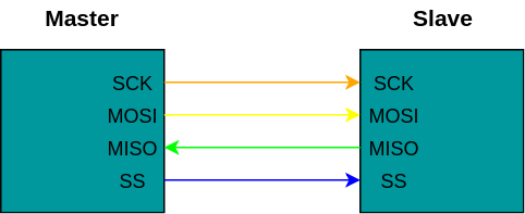
We are going to use SPI pins on Arduino UNO:
Pin 13 - SCK  - Serial Clock
Pin 12 - MISO - Master In Slave Out
Pin 11 - MOSI - Master Out Slave In
Apart from that we will need one pin for slave select (SS). We will use pin 10 for that.
We are going to make following connections:
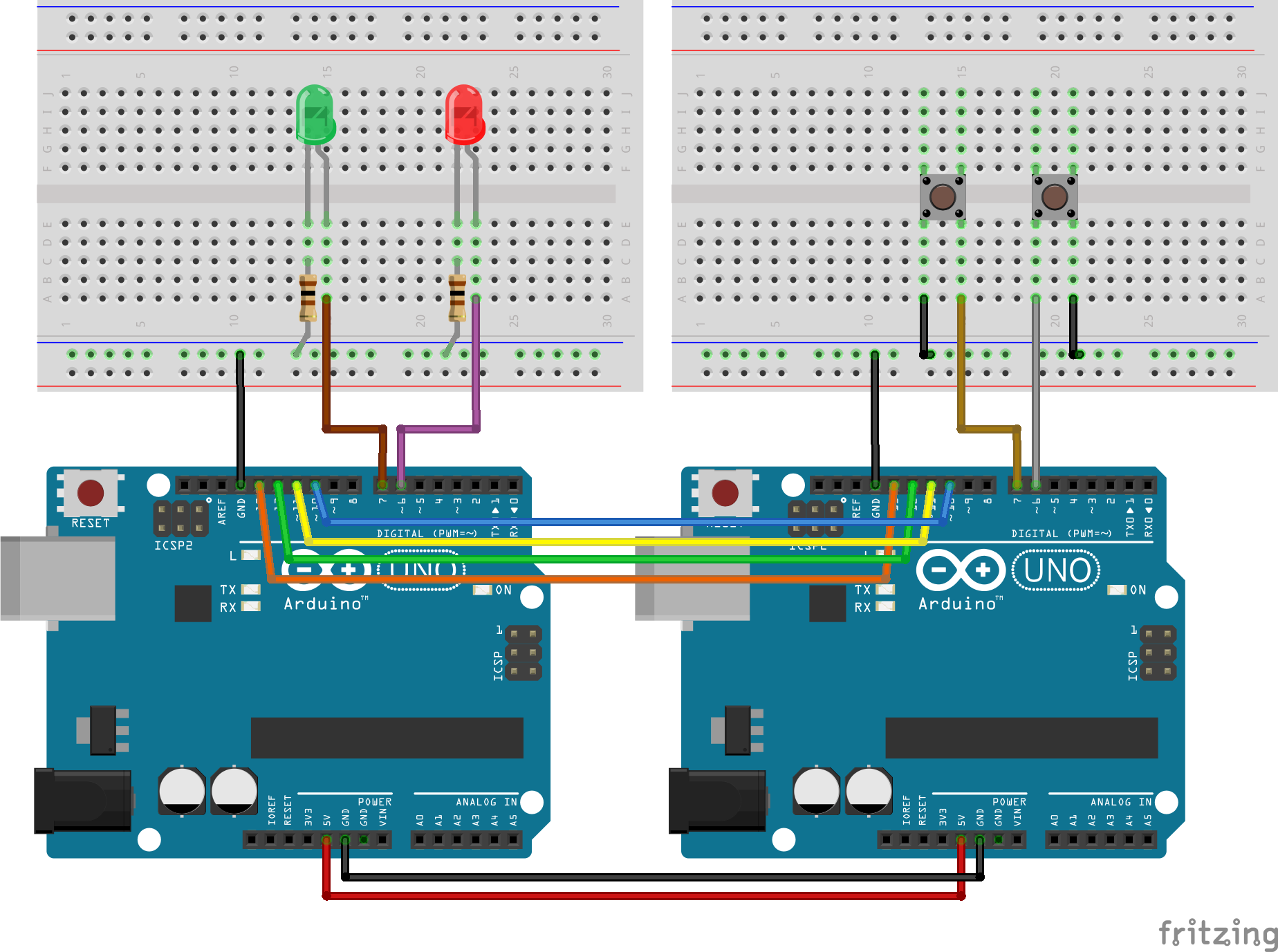
We are going to connect the LEDs to Pin 6 and Pin 7 on slave Arduino, and we are going to connect the push buttons to Pin 6 and Pin 7 on master Arduino.
Here is how the breadboard layout will look like:
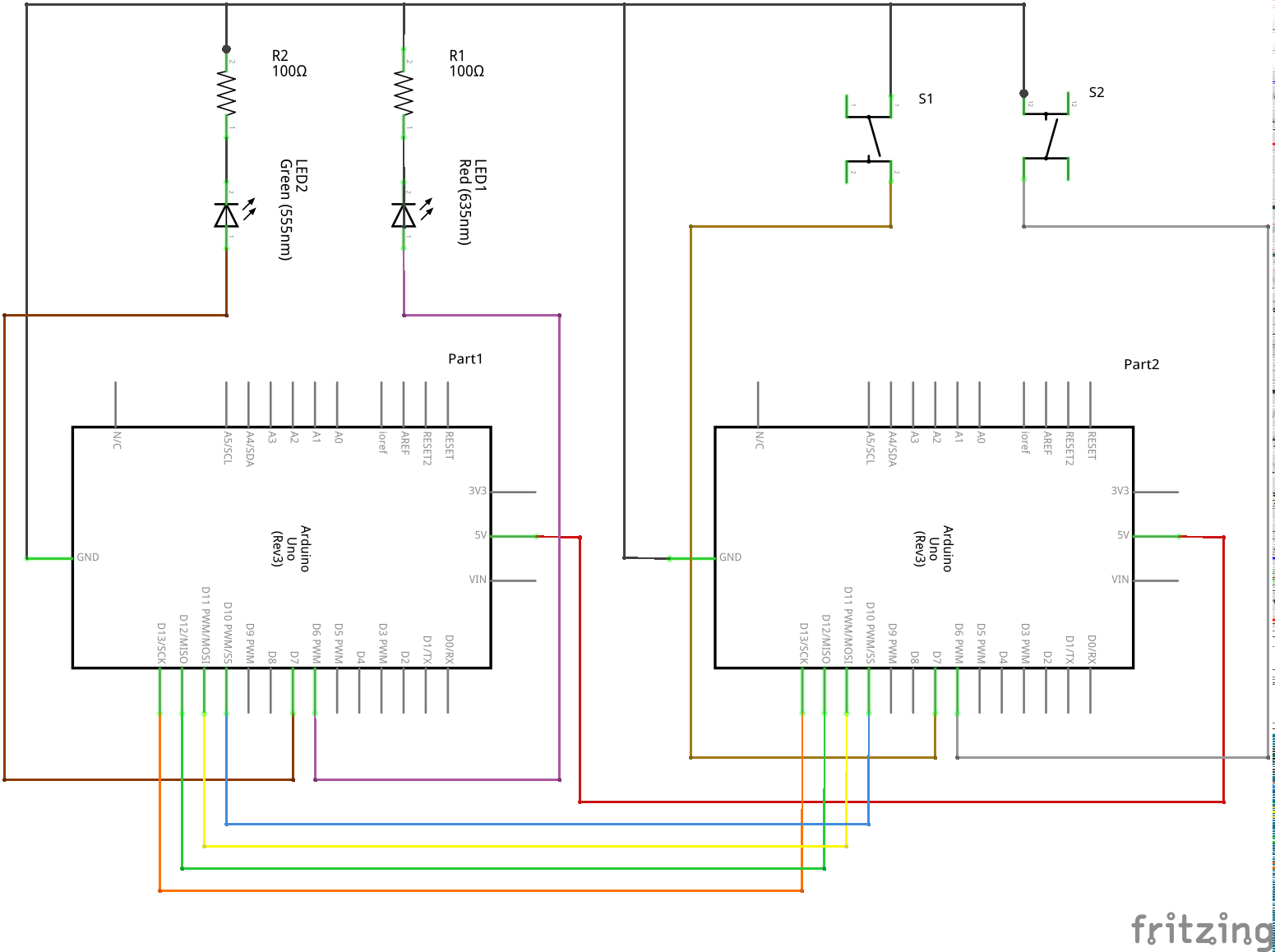
And here is the schematic for more clarity:
Programming
Code on Master Arduino (with Push Buttons)
#include <SPI.h>
#include "pins_arduino.h"

struct Button {
  int pin = 0;
  int currentState = HIGH;
  unsigned long stateSince = 0;
  int debounce = 100;
  int toggleValue = 0;
  char label = '-';
};

struct Button buttonA;
struct Button buttonB;

void setup (void) {
  // Serial for Debugging
  Serial.begin (9600);

  // Put SCK, MOSI, SS pins into output mode
  // also put SCK, MOSI into LOW state, and SS into HIGH state.
  // Then put SPI hardware into Master mode and turn SPI on
  SPI.begin ();
  SPI.setClockDivider(SPI_CLOCK_DIV8);

  // Setup button A
  buttonA.pin = 6;
  buttonA.label = 'A';
  pinMode(buttonA.pin, INPUT_PULLUP);

  // Setup button B
  buttonB.pin = 7;
  buttonB.label = 'B';
  pinMode(buttonB.pin, INPUT_PULLUP);
}

void loop (void) {
  bool buttonA_changed = buttonToggle(&buttonA);
  bool buttonB_changed = buttonToggle(&buttonB);

  if (buttonA_changed) {
    xferData(buttonA);
  }

  if (buttonB_changed) {
    xferData(buttonB);
  }
}

void xferData(struct Button button) {
  char c;

  // Enable Slave Select
  // SS is pin 10
  digitalWrite(SS, LOW);

  // Create payload
  char data[3] = {button.label, ('0' + button.toggleValue), '\n'};
  Serial.println(data);

  // Send data
  for (const char * p = data; c = *p; p++) {
    SPI.transfer (c);
  }

  // Disable Slave Select
  digitalWrite(SS, HIGH);
}


bool buttonToggle(struct Button* button) {
  bool toggleState = false;
  int reading = digitalRead(button->pin);

  if (reading == button->currentState) {
  } else {
    unsigned long int currentTime = millis();

    if (((currentTime - button->stateSince) > button->debounce)
        && button->currentState == LOW) {
      toggleState = true;
      if (button->toggleValue == 0) {
        button->toggleValue = 1;
      } else {
        button->toggleValue = 0;
      }
    }
    button->currentState = reading;
    button->stateSince = currentTime;
  }
  return toggleState;
}
Code on Slave Arduino (with LEDs)
#include "pins_arduino.h"

char buf [100];
volatile byte pos;
volatile boolean process_it;

int pinA = 6;
int pinB = 7;


void setup (void) {
  // Serial for debugging
  Serial.begin (9600);

  // Act as slave, MISO should be OUTPUT
  pinMode(MISO, OUTPUT);

  // Turn on SPI in slave mode
  SPCR |= _BV(SPE);

  // Turn on interrupts
  SPCR |= _BV(SPIE);

  pos = 0;
  process_it = false;

  // LED Output
  pinMode(pinA, OUTPUT);
  pinMode(pinB, OUTPUT);
}


// SPI ISR
ISR (SPI_STC_vect) {
  byte c = SPDR;

  // add to buffer if room
  if (pos < sizeof buf) {
    buf [pos++] = c;

    // newline means time to process buffer
    if (c == '\n') {
      process_it = true;
    }
  }
}

void loop (void) {
  // wait for flag set in ISR
  if (process_it) {
    buf [pos] = 0;
    Serial.println(buf);
    changeLed(buf);
    pos = 0;
    process_it = false;
  }
}

// update LED output
void changeLed(char * buf) {
  int pin, value;

  if (buf[0] == 'A') {
    pin = pinA;
  } else if (buf[0] == 'B') {
    pin = pinB;
  } else {
    return;
  }

  if (buf[1] == '1') {
    value = HIGH;
  } else if (buf[1] == '0') {
    value = LOW;
  } else {
    return;
  }

  digitalWrite(pin, value);
}
Next Steps
I have used SPI.setClockDivider() method, which is not deprecated in favor of SPI.beginTransaction() method. I would like to modernize the code to use the new function.
In this demo I have picked two Arduino UNOs to get SPI to work. I worked out great becacuse both Arduinos share the same clock speed i.e. 16 MHz. I would do a SPI demo with two heterogeneous systems. So, I would like to do SPI between Arduino UNO and a Raspberry Pi.
Feel free to tweet me if you like/hate my content.