ATmega328P SPI Slave Mode Debugging through Serial Console
Introduction
Over the last couple of posts, I have built prototypes to run SPI between two Arduino UNOs and the setup was relatively straightforward.
Now, I want to setup SPI between two different types of boards, and I realized that I am not very familiar with Arduino Due, and interfacing that with Arduino UNO over SPI may not be as straighforward. Arduino UNO pins run at 5v logic level, and Arduino Due pins run at 3.3v logic level. I am not sure that Due will support 5v logic on SPI pins, or ATmega328 i.e. UNO’s microcontroller can run properly at 3.3v supply. I have noticed that ATmega328 SPI starts misbehaving at lower voltages in the past.
And, because of this, I decided to install an ATmega328P microcontroller with a SPI to Serial Console proxy with following parameters:
- 5v Power Supply
- Master SPI Clock rate should be either 1MHz or 2Mhz.
- Bit Order is
MSBFIRST. - Data Mode is
SPI_MODE0.
I will use this setup, interface it with Arduino Due for debugging.
In this post, I will cover how to setup a SPI to Serial Console Proxy on a ATmega328P chip.
Parts needed
I used the following parts for this setup.
- ATmega328P 28-pin DIP IC
- 16 MHz Crystal and Capacitor Set
- USBtinyISP
- USB to TTL Serial Cable
- Arduino UNO (for testing)
and, breadboard, jumper cables, USB A-male to B-male cable, etc.
SPI to Serial Proxy Setup
I used USBtinyISP to program the Arduino UNO bootloader to a blank ATmega328P microcontroller, and then program the proxy code into it. There are several articles available online on how to do that, so I am not going to cover that here.
I have named this program echo-chamber because it echos data to UART pins of everything it receives on SPI pins.
Here is the code. I have documented at places where I felt necessary.
// Allocate 256 bytes as a cyclic buffer
// Received SPI data will be enqueued into this buffer through ISR
// We will dequeue the data and transmit it to serial monitor in the main loop
#define FULL 256
byte queue[FULL];
int head=0;
int tail=0;

// Global Constants
const char h1_sep[15] = "--------------";
const char asciimap[34][4] = {
  "NUL",
  "SOH",
  "STX",
  "ETX",
  "EOT",
  "ENQ",
  "ACK",
  "BEL",
  "BS ",
  "TAB",
  "LF ",
  "VT ",
  "FF ",
  "CR ",
  "SO ",
  "SI ",
  "DLE",
  "DC1",
  "DC2",
  "DC3",
  "DC4",
  "NAK",
  "SYN",
  "ETB",
  "CAN",
  "EM ",
  "SUB",
  "ESC",
  "FS ",
  "GS ",
  "RS ",
  "US ",
  "SPC",
  "DEL"
};

volatile boolean process_it;

void setup (void) {
  // Serial for debugging
  Serial.begin(115200);

  // Act as slave, MISO should be OUTPUT
  pinMode(MISO, OUTPUT);

  // Turn on SPI in slave mode
  SPCR |= _BV(SPE);

  // Turn on interrupts
  SPCR |= _BV(SPIE);

  // CLK = 8 MHz
  // (Master should transmit data 0.25x speed or less)
  //SPCR |= _BV(SPR1);
  SPSR |= _BV(SPI2X);

  process_it = false;

  // Startup message
  // This will help detect restarts
  Serial.println(h1_sep);
  Serial.println(" Echo Chamber");
  Serial.println(" Started!");
  Serial.println(h1_sep);
}


// SPI ISR
ISR (SPI_STC_vect) {
  process_it = false;
  byte c = SPDR;
  queue[tail] = c;
  tail = nextIndex(tail);
  process_it = true;
}

void loop (void) {
  // wait for flag set in ISR
  if (process_it) {
    // print header
    Serial.println(h1_sep);
    Serial.println(" ASCII\tChar");
    Serial.println(h1_sep);

    // print buffer
    while(head != tail) {
      int ascii_code = queue[head];

      // print row
      Serial.print(" ");
      Serial.print(ascii_code);
      Serial.print("\t");
      if (ascii_code <= 32) {
        Serial.println(asciimap[ascii_code]);
      } else if (ascii_code == 127) {
        Serial.println(asciimap[33]);
      } else {
        Serial.println((char) queue[head]);
      }

      queue[head] = 0;
      head = nextIndex(head);
    }

    process_it = false;
  }
}


// This will allow us to cycle through the
// 256 bytes buffer
int nextIndex(int index) {
  if (index == FULL - 1) {
    return 0;
  } else {
    return index + 1;
  }
}
Burn the above code to the microcontroller, and it will start accepting data over SPI, and it will proxy that to Serial Interface (RX, TX pins). Connect the board to a serial console cable and you should be able to see that data on Arduino’s Serial Monitor, PuTTY or Screen at 115200 baud rate.
You can use the following command on screen (assuming your Console Cable is
/dev/ttyUSB0).
screen /dev/ttyUSB0 115200
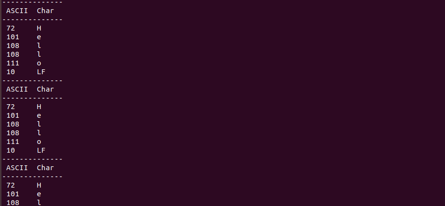
I connected this microcontroller to an Arduino UNO loaded with the following code that resulted in the hero image of this article.
#include <SPI.h>
#include "pins_arduino.h"

int SSPin = 10;

SPISettings spiSettings(1000000, MSBFIRST, SPI_MODE0);

void setup (void) {
  // Serial for Debugging
  Serial.begin (9600);

  // Put SCK, MOSI, SS pins into output mode
  // also put SCK, MOSI into LOW state, and SS into HIGH state.
  // Then put SPI hardware into Master mode and turn SPI on
  SPI.begin();

}

void loop (void) {
  xferData();
  delay(1000);
}

void xferData() {
  char c;

  SPI.beginTransaction(spiSettings);

  // Enable Slave Select
  // SS is pin 10
  digitalWrite(SSPin, LOW);

  // Create payload
  char data[6] = {'H', 'e', 'l', 'l', 'o', '\n'};
  Serial.println(data);

  // Send data
  for (const char * p = data; c = *p; p++) {
    SPI.transfer(c);
  }

  // Disable Slave Select
  digitalWrite(SSPin, HIGH);
  SPI.endTransaction();
}
Next, I am planning to interface this microcontroller to Arduino Due.
Stay tuned and feel free to tweet me if you like/hate my content.